Animating the camera and other parameters
OVITO offers powerful animation capabilities that allow you to animate the virtual camera, modifiers, and visual parameters. This section explains the animation system in detail.
Animation frames vs. trajectory frames
When you load a simulation trajectory into OVITO, the timeline below the viewport indicates the animation length. Animation frames in OVITO start at 0, meaning an animation ending at frame 100 consists of 101 frames.
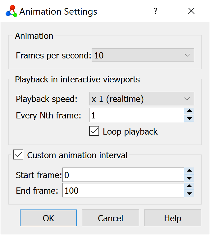
There is a key distinction between trajectory frames (snapshots from a simulation) and animation frames (units of time in OVITO’s timeline). By default, OVITO maps trajectory frames one-to-one to animation frames and the length of the animation timeline matches the number of imported trajectory frames. However, you can override this in the Animation settings dialog and set the animation length manually. Extending the animation interval beyond the available trajectory frames results in additional static frames at the end of the rendered video.
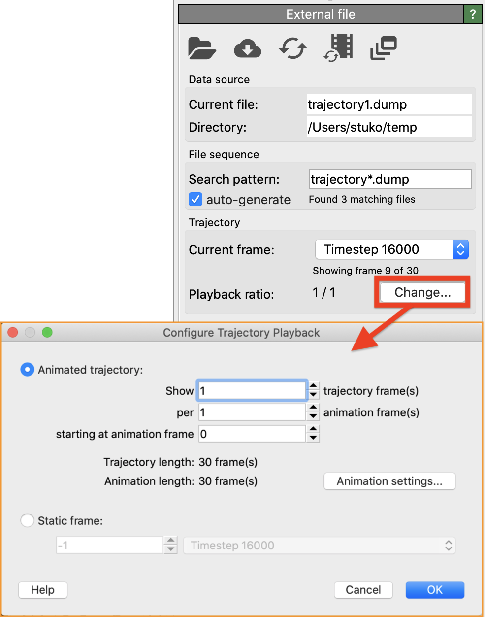
Further control over how trajectory frames map to animation frames is provided in the Configure trajectory playback dialog, which is shown in the screenshot on the right. This dialog is accessible from the External file panel (pipeline data source).
The Playback rate setting allows you to adjust the frame mapping. For instance:
A rate of 1/2 stretches the trajectory over twice as many animation frames, making each simulation snapshot persist for two consecutive frames.
A rate of 2/1 compresses the trajectory, skipping every other simulation frame in the animation.
The Starting at animation frame setting determines when the simulation trajectory playback begins in OVITO’s timeline. By default, it starts at frame 0, but you can change this to insert static frames at the beginning.
OVITO Pro also supports inserting multiple simulation trajectories into a single scene to display them side by side or layered. By default, the timeline automatically adjusts to accommodate all loaded trajectories (respecting their individual playback rates and starting times).
See also
Playback speed
In the Animation settings dialog, you can set the playback speed (frames per second) for the animation. This value determines the frame rate of exported video files (e.g., AVI, MPEG). It also affects viewport playback, though real-time performance may be limited by how quickly OVITO can load simulation snapshots from disk and process them.
Using time-dependent formulas
Basic animation effects can be achieved using the Expression selection and Compute property modifiers. These allow you to use mathematical formulas or Boolean expressions to manipulate particle properties (e.g., position, color, transparency) and create dynamic selection sets.
You can incorporate the special variable Frame in expressions, which represents the current animation frame number.
Using this variable makes expressions time-dependent, meaning OVITO will recompute them for each animation frame.
Keyframe-based animations
OVITO supports keyframe-based animations, where you define values for animatable parameters at specific frames (e.g., at the start and end of an animation). The software interpolates between these keyframes, typically using linear interpolation.
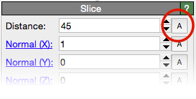
The screenshot on the right shows the parameter panel for the Slice modifier. Animatable parameters are marked with an A button next to the input field. Clicking this button opens the animation key dialog, allowing you to define time-value pairs (animation keys).
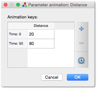
For example, in the screenshot, two keyframes are set for the Distance parameter of the slicing plane:
Frame 0 –> value 20.0
Frame 50 –> value 80.0
This setup ensures a smooth transition from 20.0 to 80.0 over the animation interval. Every animatable parameter has at least one keyframe. With a single keyframe, the parameter remains constant. Adding a second keyframe enables animation through interpolation.
Auto-key mode
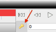
The animation toolbar next to the time slider features a button that activates Auto-key mode.
When enabled, the time slider background turns red. Any change you make to an animatable parameter while this mode is active automatically generates a keyframe at the current animation time.
Example workflow:
Activate Auto-key mode.
Move the time slider to frame 0 and set the Distance parameter of the Slice modifier to 20.
Move the time slider to the final frame of the animation and set the parameter to 80.
OVITO automatically creates keyframes at these points of the timeline.
Remember to turn off Auto-key mode again once you’ve finished creating the animation keys to prevent unintended changes. The Auto-key mode is a convenient alternative for creating new animation keys, which can be quicker than using the animation key dialog introduced in the previous section.
The animation track bar
The track bar beneath the time slider displays keyframes for the selected pipeline and all its animated parameters:
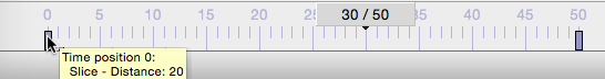
Each keyframe appears as a small marker on the timeline. Hovering over a marker reveals keyframe details. You can:
Drag keyframes to reposition them.
Right-click to open a context menu and delete them.
The track bar shows markers only for animated parameters (i.e., those with at least two keyframes). Parameters with a single keyframe remain constant and do not appear in the track bar.
Animating the camera
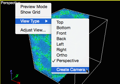
To animate the camera, first create a camera object from a viewport’s context menu (see screenshot). The camera object is placed in the 3D scene at the current viewpoint and is linked to the viewport.
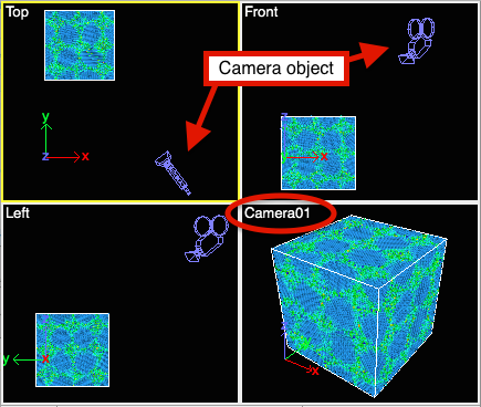
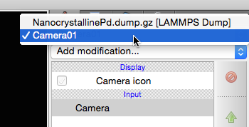
The camera object is visible in the other three viewports. Zoom out if necessary. Select the camera by clicking on it in a viewport or using the object selector box in the top-right corner of the main window:
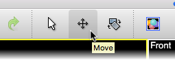
Use the Move and Rotate tools in the main toolbar to adjust the camera position and orientation:
While using these tools, you can:
Drag the camera object with the mouse.
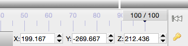
Enter precise position and rotation values in the numeric input fields located in the status bar:
Like other scene objects, the camera’s position and orientation can be animated using keyframes. To do this:
Enable Auto-key mode.
Move the time slider to a different animation time and adjust the camera’s position.
OVITO automatically creates keyframes, animating the camera along an interpolated path.
The track bar displays camera animation keys when the camera is selected.
Instead of moving the camera, you can also animate the simulation model (e.g., by rotating it). This is done similarly: Select the simulation model and use the Rotate tool while Auto-key mode is active. See the tutorial Turntable animation of a model for more information.