Simulation cell
This page of the data inspector displays information about the simulation cell of the current dataset. The simulation cell defines the spatial domain of the atomistic or particle-based simulation and specifies whether periodic boundary conditions are enabled along each spatial direction.
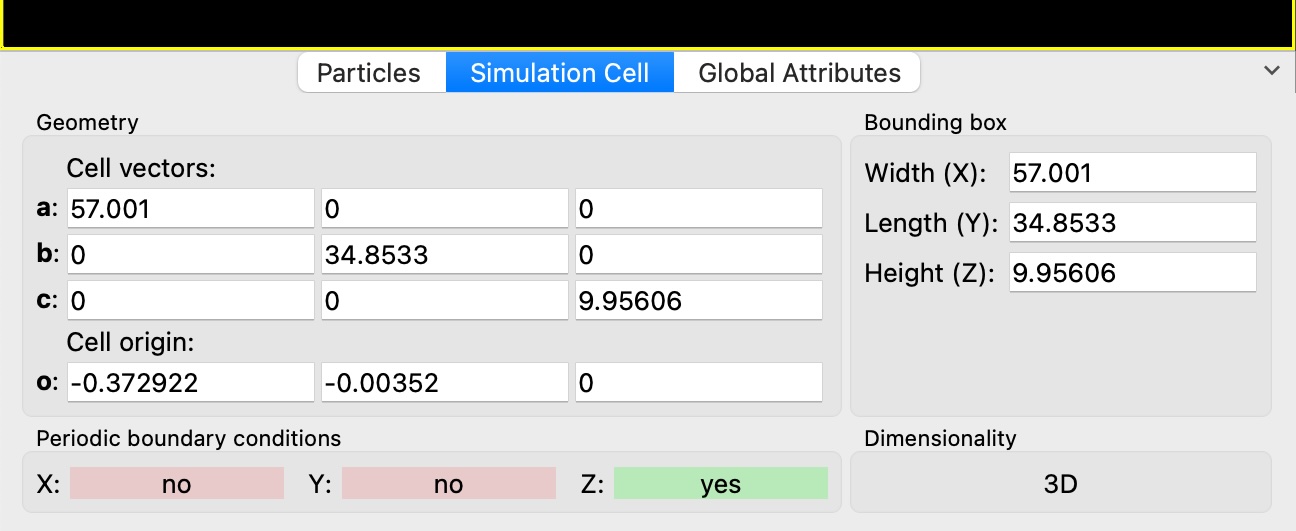
The page is divided into four sections:
- Geometry
Displays geometric information about the simulation cell in one of two modes, which can be toggled using a control in the panel header:
Cell vectors: Shows the three vectors \(\bf{a}\), \(\bf{b}\), and \(\bf{c}\) that define the edges of the simulation cell, as well as the cell origin \(\bf{o}\). Each vector is displayed as a triplet of X, Y, Z components in the global Cartesian coordinate system. The cell vectors form a parallelepiped and do not need to be orthogonal; they can have arbitrary lengths and angles to represent non-orthogonal simulation domains (e.g., triclinic cells).
Cell parameters: Shows the magnitudes (lengths) of the three edge vectors \(|\bf{a}|\), \(|\bf{b}|\), and \(|\bf{c}|\), as well as the angles between them: \(\alpha\) (angle between \(\bf{b}\) and \(\bf{c}\)), \(\beta\) (angle between \(\bf{a}\) and \(\bf{c}\)), and \(\gamma\) (angle between \(\bf{a}\) and \(\bf{b}\)). This representation is commonly used in crystallography to describe unit cell geometry.
- Bounding box
Shows the dimensions of the axis-aligned bounding box that encloses the simulation cell. The width, length, and height values represent the extent of the cell along the X, Y, and Z coordinate axes, computed from the cell vectors. Note that these values are only meaningful for orthogonal cells that are aligned with the coordinate axes.
- Periodic boundary conditions
Indicates which spatial directions have periodic boundary conditions (PBC) enabled. Note that the PBC flags labeled as X, Y, and Z actually refer to the three cell vectors, which are not necessarily aligned with the coordinate axes in case of non-orthogonal cells.
- Dimensionality
Indicates whether the simulation is two-dimensional (2D) or three-dimensional (3D). In 2D mode, the Z-coordinates of particles and the third simulation cell vector are ignored in most calculations.
Hint
The information shown in the data inspector is read-only and reflects the state of the simulation cell at the end of the current data pipeline. To modify the simulation cell geometry in OVITO, use the Edit simulation cell or Affine transformation modifiers in the data pipeline. The Edit in pipeline… button provides a convenient way to insert an Edit simulation cell modifier into the current pipeline.
Note
If the imported simulation file does not contain any cell information, this tab is not shown in the data inspector. You can turn on the option Generate bounding box if needed in the settings of the file reader to let OVITO generate an ad-hoc simulation cell that tightly encloses all imported particles in an axis-aligned bounding box.
See also