Edit simulation cell
Added in version 3.15.0.
This modifier lets you modify the simulation cell geometry and boundary conditions. By inserting an Edit Simulation Cell modifier into a data pipeline you can:
Change the cell’s dimensionality (2D or 3D).
Toggle periodic boundary conditions in the X, Y, and Z directions.
Override the cell geometry by specifying new cell vectors and origin.
You can use this modifier to adjust the simulation cell parameters that were originally loaded from the simulation file, e.g., to enable or disable periodic boundary conditions in specific directions, switch between 2D and 3D representations, or modify the cell shape and size for visualization or analysis purposes.
Keep in mind that changes made with this modifier take effect only at the position in the pipeline where the modifier is inserted. That means only downstream modifiers and visualizations will see the modified simulation cell.
Tip
You can always inspect the final simulation cell state, i.e., the state at the end of the data pipeline, on the Simulation Cell page of the data inspector. From there, you can also use the Edit in pipeline… button to conveniently insert an Edit Simulation Cell modifier into the current pipeline.
Modifier settings
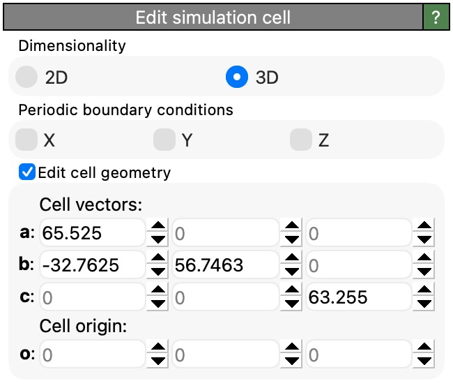
- Dimensionality
Choose between 2D and 3D simulation cell representations. In 2D mode, the periodic boundary condition in the Z direction is automatically disabled and cannot be toggled.
- Periodic boundary conditions
These checkboxes control whether the simulation cell has periodic boundary conditions in the X, Y, and Z directions. When a direction is periodic, particles that leave the cell on one side reappear on the opposite side. In 2D mode, the Z periodic boundary condition is disabled.
- Edit cell geometry
When this group box is enabled, the modifier will override the input cell geometry with the specified cell vectors and origin. When disabled, the modifier only changes the dimensionality and periodic boundary conditions but leaves the cell geometry unchanged.
- Cell vectors
The three cell vectors a, b, and c define the parallelepiped shape of the simulation cell. Each vector is specified by its three Cartesian components (X, Y, Z).
- Cell origin
The origin o specifies the position of one corner of the simulation cell in 3D space. This vector defines the translation component of the cell matrix.
See also
Simulation cell data object
Affine transformation modifier
Replicate modifier
Simulation cell data inspector
ovito.data.SimulationCell(Python API)