Particles
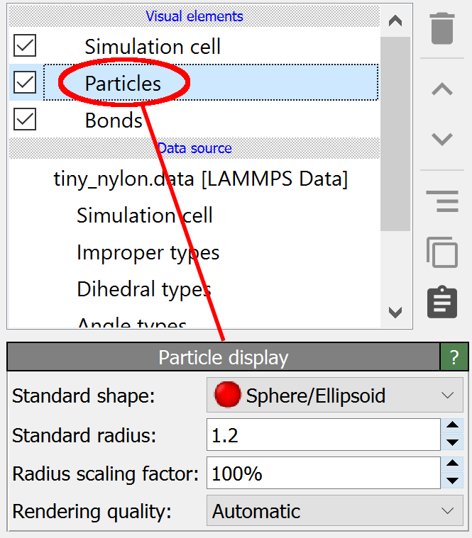
This visual element is responsible for rendering the particles. Typically, particles are visualized as simple spheres, but you can switch to other, more complex geometric shapes if desired. The Particles visual element provides parameters controlling the standard visual representation of particles.
Settings hierarchy
OVITO uses a three-level hierarchy to determine the final appearance of each individual particle:
Per-particle properties (highest priority): Properties like
Color,Radius, andTransparencydefined for individual particles always take precedence if present. See Per-particle properties below for details.Per-type settings (medium priority): Settings configured for each particle type through the Edit types modifier. These include type-specific radius, color, and shape. Per-type settings can also include custom mesh shapes for advanced visualizations.
Default settings (lowest priority): The default particle shape and radius values configured in this visual element serve as the final fallback.
This hierarchy allows flexible control: you can set defaults that work for most particles, customize specific types (e.g., different radii for different atomic species), and still override individual particles when needed (e.g., highlighting specific atoms using selection and coloring modifiers).
To modify these settings:
Per-particle properties: Use the Compute property modifier or more specific coloring modifiers
Per-type settings: Use the Edit types modifier
Default settings: Configure them directly in this visual element panel
Per-particle properties
On the primary level, the visualization is affected by certain properties of the particles themselves, listed in the following table. By setting these particle properties, for example using the Compute property modifier, you can fully control the visualization on a per-particle basis.
Particle property |
Data type |
Description |
|---|---|---|
|
Real (R,G,B) |
Display color of individual particles. Red, green, and blue components must be in the range [0,1]. |
|
Real |
Display size on a per-particle basis. |
|
Real |
Transparency of individual particles. Must be in the range [0,1]. |
|
Real (X,Y,Z) |
Dimensions of particles with a non-spherical shape. The exact interpretation depends on the particle shape. |
|
Real (X,Y,Z,W) |
3D rotation of particles with non-symmetric shapes, specified as a quaternion. See Controlling size and orientation of particles for further information. |
|
Real (X,Y) |
Roundness parameters for superquadric particles. |
|
Integer |
Marks currently selected particles (1 = selected, 0 = unselected). Selected particles are highlighted in red (only in interactive viewports but not in rendered images). |
To see the list of particle properties present in your dataset, open the data inspector panel.
Parameters
Universal settings
These settings apply globally to all particles in the system:
- Radius scaling
This global scaling factor (percentage) is applied to all particle radii at rendering time. It is applied in addition to any other factors controlling the size of particles (per-type radius, per-particle radius, default radius). By setting it to a value below 100%, you can generate a ball-and-stick visualization of molecular systems, with reduced atomic spheres connected by cylindrical bonds.
- Rendering quality
This parameter controls the method used for rendering spherical particles in the interactive viewports using the Standard renderer. The following modes are available:
- Automatic (default)
OVITO automatically selects the rendering quality based on particle count:
Less than 4,000 particles: High quality
Between 4,000 and 400,000 particles: Medium quality
More than 400,000 particles: Low quality
High quality is always used for final output images regardless of particle count
- Low
Particles are rendered as texture-mapped impostors facing the viewer. Particles do not have depth in this mode, and intersections between overlapping particles may not be displayed correctly. This mode offers the best performance.
- Medium
Particles are rendered as texture-mapped impostors facing the viewer. A GPU fragment shader computes depth information for each pixel to produce reasonable sphere-sphere intersections for overlapping particles.
- High
Particles are rendered as true spheres using a GPU fragment shader that computes the ray-sphere intersection for every rendered pixel. This provides the best visual quality.
Default particle shape
These settings provide default values for particles that do not have shape or size specified via per-type settings or per-particle properties:
- Style
Selects the default display shape for particles. The shape can be overridden on a per-type basis (see the note above about the property hierarchy). Available shapes:
- Sphere/Ellipsoid
Particles are rendered as 3D spheres by default. This mode supports several advanced variations:
With
Aspherical Shapeproperty: Particles become ellipsoids where the three components (X,Y,Z) control the half-lengths of the principal axes (theRadiusproperty is ignored).With
Superquadric Roundnessproperty: Particles are rendered as superquadrics with controllable roundness.The particle’s
Orientationproperty, if present, rotates the ellipsoid or superquadric.
- Circle
Particles are rendered as flat discs that always face the viewer. Note that some rendering engines may not support this mode.
- Cube/Box
Particles are rendered as cubes by default, with the
Radiusproperty controlling the edge half-length.With
Aspherical Shapeproperty: Particles become rectangular boxes where the three components (X,Y,Z) specify the half-lengths along each axis.The particle’s
Orientationproperty, if present, rotates the box.
- Square
Particles are rendered as flat squares that always face the viewer. Note that some rendering engines may not support this mode.
- Cylinder
Particles are rendered as cylinders aligned along the Z-axis by default.
The
Aspherical Shapeproperty is required: its X-component controls the cylinder radius, its Z-component controls the cylinder length.The
Orientationproperty rotates the cylinder from its default Z-axis alignment.
- Spherocylinder
Particles are rendered as cylinders with hemispherical caps (capsules). Configuration is identical to the Cylinder mode above.
- Radius
Specifies the default particle size (in simulation distance units) used as a fallback when the size is not specified via per-particle or per-type settings. This value is only used for particles where:
The
Radiusparticle property is absent or zero, ANDThe particle’s type (from
Particle Typeproperty) has no radius defined or has radius = 0
Virtual periodic images
This option completes the visual appearance of a periodic structure at the boundaries of the simulation cell. When the option is enabled, OVITO renders additional copies of particles located near the periodic cell boundaries, together with their bonds and vector arrows. An atom sitting exactly on a corner of the cell, for instance, is then shown at all eight corners, and a bond crossing a periodic boundary appears whole instead of being split into two stubs.
The virtual images are generated by the renderer only. In contrast to the Replicate modifier, no new elements are added to the data collection: the number of particles reported by the data inspector and by any analysis modifier remains unchanged. You can still pick a virtual image with the mouse; OVITO resolves it to the original particle or bond it was generated from. Images are generated only along those directions for which periodic boundary conditions are enabled; the option is unavailable if the simulation cell has no periodic boundary conditions at all.
Mesh regions anchored to particles follow the virtual images of their particles as well: the coordination polyhedra around the cations of a crystal, the ring polygons found by the Find rings modifier, and the cells constructed by the Voronoi analysis modifier. Such a region is drawn as one rigid body wherever its anchor particle (the central atom of a polyhedron, the first atom of a ring) is drawn, so that the polyhedra and rings of the virtual particle images appear complete. While virtual images are shown, these regions are not cut at the periodic cell boundaries, irrespective of the Wrap at periodic boundaries option of the Surface mesh visual element.
The check box in the title of the Virtual periodic images group box turns the rendering of periodic images on or off (off by default). When enabled, the following settings control which particles are replicated across the periodic boundaries:
- Replication mode
One of three radio buttons selects the rule that decides which particles are replicated. The boundary region defined by the Padding width applies in all modes; the two bond-based modes add further particles to the picture and therefore require bonds to be present, e.g. generated by the Create bonds modifier. They are unavailable if the input contains no bonds.
- Boundary region only
Particles located exactly on the cell boundaries or within the padded boundary region (if padding width > 0%) are replicated. Use this mode to show virtual images of atoms that are located on the edges of the periodic cell.
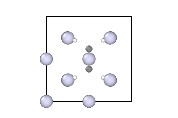
Replication mode: Off (original cell)
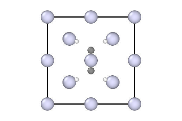
Replication mode: Boundary region only
- Complete bonded neighbors
In addition to particles exactly on the boundary, every drawn particle acting as the center of a bond pulls its bonded neighbor (the ligand) into the picture, even if the neighbor lies outside the boundary region. This completes the coordination environments of the atoms in the primary cell and is intended for inorganic crystals, where it makes the coordination polyhedra of the cations appear complete. A particle pulled into the picture in this way pulls in its own ligands in turn, so that, for example, the hydrogen of a hydroxyl group follows its oxygen. Bonds between equivalent particles are followed one step only, which keeps the picture from growing indefinitely.
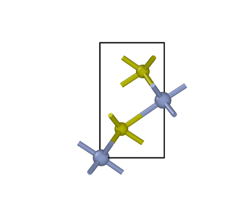
Replication mode: Off (original cell)
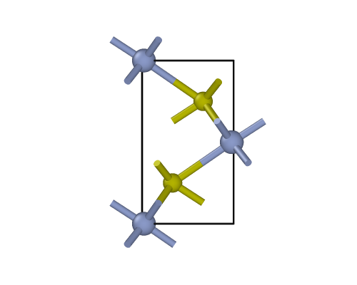
Replication mode: Boundary region only
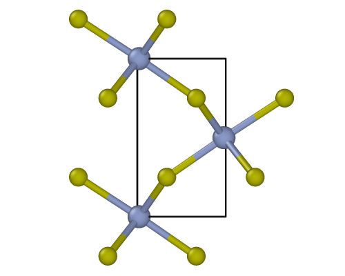
Replication mode: Complete bonded neighbors
Whether a particle acts as the center or the ligand of a bond is decided automatically: the particle with the higher number of bonds is the center. If both particles have the same number of bonds, the chemical elements decide: in a bond between a metal and a typical anion-forming element (H, N, O, F, P, S, Cl, As, Se, Br, Te, I) the metal is the center, e.g. Na in a Na-Cl bond of a rock salt structure; between two elements of the same kind, the less electronegative one is the center. If the elements are the same or unknown, the bond is completed in both directions. In this mode, a half-bond pointing to a particle that is not drawn is hidden, so that no dangling bond stubs protrude from the picture.
- Complete molecules
Every molecule (i.e., connected group of bonded particles) with at least one particle drawn is drawn as a whole. Molecules cut by a cell boundary therefore appear complete on both sides of the boundary. This mode is intended for molecular crystals. Molecules forming an infinite network across the periodic boundaries, as is the case in covalent or ionic crystals, cannot be drawn as a whole; they are completed using the bonded-neighbor rule instead, and OVITO reports a warning in the pipeline editor. As in the previous mode, dangling half-bonds are hidden.
Tip
This mode renders every molecule cut by a cell boundary twice, once on each side of the boundary. If you would rather see each molecule just once, but in one piece, do not use this replication mode. Instead, insert a Cluster analysis modifier into the pipeline, set it to the bond-based neighbor mode and enable its Unwrap particle coordinates option. This joins the fragments of each molecule by translating particles across the periodic boundaries, so the molecule appears as a contiguous object sticking out of the cell on one side only.
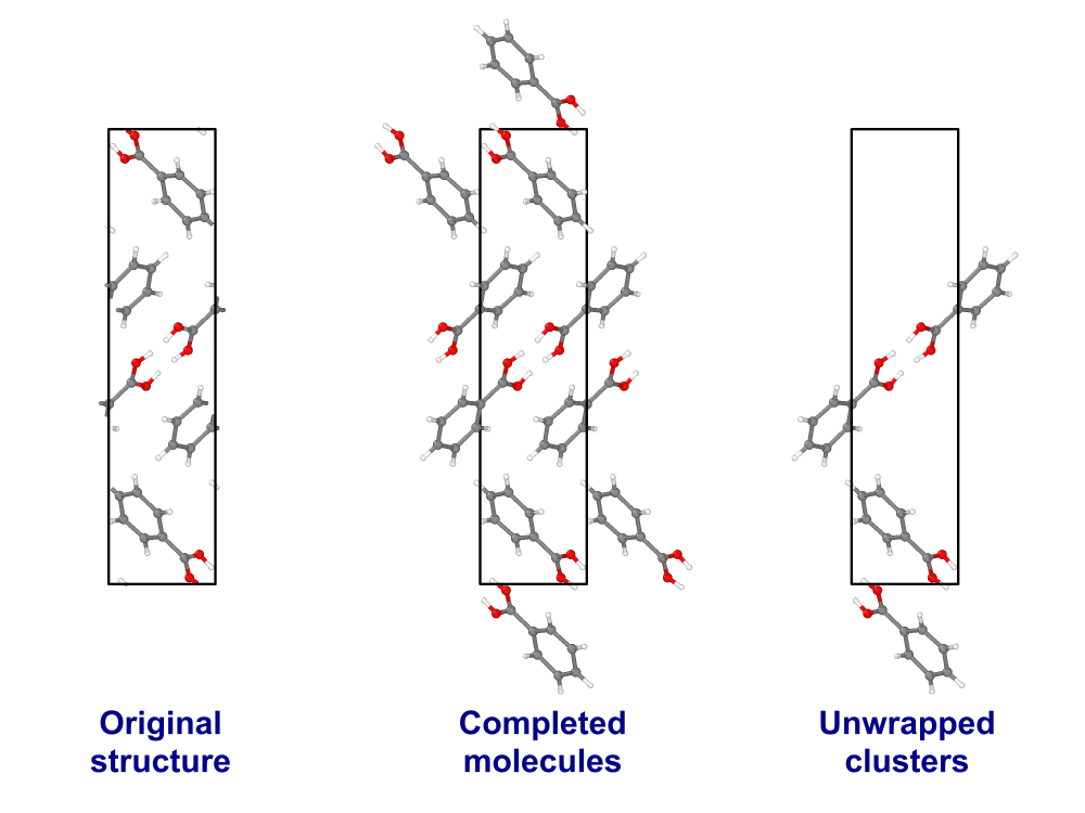
Two ways of dealing with molecules cut by the periodic cell boundaries: the Complete molecules replication mode shows each cut molecule in full on both sides of the boundary (center), whereas the Cluster analysis modifier allows to show a single copy of each molecule in one piece (right).
- Padding width
The width of the boundary region from which virtual periodic images are generated, as a percentage of the cell length along each of the three cell vectors. A particle is duplicated into a neighboring cell if its image comes to lie within this distance of the primary cell. Atoms sitting exactly on the cell faces, edges and corners are replicated even with the default value of 0%. Increase the value to show a thicker shell of surrounding structure. The value is capped at 100%, i.e. images are never generated beyond the 26 directly adjacent cells.
See also
ovito.vis.ParticlesVis (Python API)